A Quick Guide to Optical Fiber
Optical fiber doesn’t quite have the mystique that used to surround it but the technology is still quite different from the familiar copper wire based Ethernet cabling. Optical fiber cabling and the support equipment provide a set of trade-offs compared to copper cabling; whether optical fiber is the optimal choice depends on the requirements.
What is Optical Fiber?
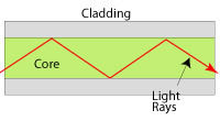
Instead of carrying signals as electrical impulses along copper wire like Ethernet or coaxial cabling, optical fibers transmit signals using light representing much greater transmission speeds. The physics behind the technology has grown fairly complex since its debut but the basic principle remains the same. A phenomenon known as Total Internal Reflection allows light to be carried along a long thin strand of clear glass or plastic even when the strand is coiled up or curved in a myriad of directions. When this phenomenon occurs, light simply reflects off of the sides of the inner core of an optical fiber until it comes out the other end. By using light instead of electricity to carry information, a number of limitations with copper are completely mitigated.
What Does This Mean?
There are quite a few limitations with copper that can be avoided by using optical fiber. In particular, electromagnetic effects such as cross-talk and external interference are completely removed since light isn’t subject to these at all. Other important advantages of optical fiber include lighter weight and thinner cables.
Since optical fibers don’t use electricity, the cables won’t conduct electricity. This means that there’s no danger of accidentally shorting anything out. Furthermore, there can’t be any sparking which means optical fiber is the prime choice in an environment with volatile vapors (gas stations might be an example).
Finally, modern fibers made of high quality glass are capable of transmitting tremendous distances before the use of optical amplifiers or repeaters is needed. As a comparison, the maximum segment length of Ethernet cabling is 100m but 2km runs of fiber are possible. For some applications, such as data trunks used by telecoms, copper lines might go to a couple kilometers but fiber in similar situations would run to 100km! It’s an entire world of difference here.
Using Optical Fiber
While the physics of optical technology is markedly different from copper, the practical applications resemble traditional copper methods. At the endpoints there are transmitters and receivers (often combined into transceivers) while cabling runs between them punctuated by repeaters. In addition, gigabit interface convertors (GBIC) can be used to link switches using fiber with all the advantages fiber provides (particularly distance).
Optical Fiber Cables
There are a number of standard fiber types and connectors. They each have their own advantages and disadvantages and are thus suitable for different applications. We will limit the scope to the types available from Lin Haw.
Simplex and Duplex
When optical fiber is used, the light beam carrying data is only sent down the fiber in one direction. Therefore, if you need data to flow in both directions, two fibers are needed. A simplex cable is a single fiber while duplex cables have two fibers (and thus two connectors at each end).
Multi and Single Mode
The underlying physical differences between these are academically interesting but only the practical differences will be outlined. This may seem strange but thinner Single Mode fibers are capable of greater speeds and distances than the thicker Multi Mode fibers. They are also more expensive in all aspects ranging from transceivers, connectors to the fibers themselves as well as much stricter connection tolerances. Another important concern is how the thinner core is more fragile than thicker Multi Mode fiber. Nonetheless, for relatively shorter ranged applications or patch cables, Multi Mode cabling is still capable of great speeds, holding all the common advantages optical fiber has over copper.
Connectors
There are four connectors readily available from Lin Haw: SC, ST, LC and MT-RJ. These are some of the most commonly used connectors that will be found in wild.
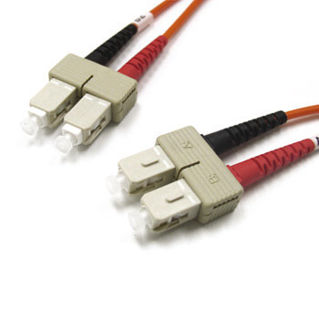
Square Connectors (SC) are a boxy and very commonly used connector. This connector is quite robust with a plastic box protecting the connector. The design also snaps in so they won’t come loose accidentally. These connectors would be commonly found on media convertors.
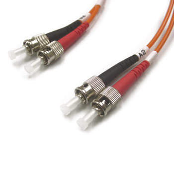
Straight Tips (ST) simply slide into the corresponding. They are relatively simple in construction and latch on with twist very similar to how BNC connectors work.
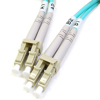
LC stands for Lucent Connectors but is more easily remembered as Little Connectors resembling miniature versions of SC connectors. Since these snap-ins are smaller than SC connectors, they are suited for situations where more connectors need to be packed into a space. GBICs in particular use these connectors.
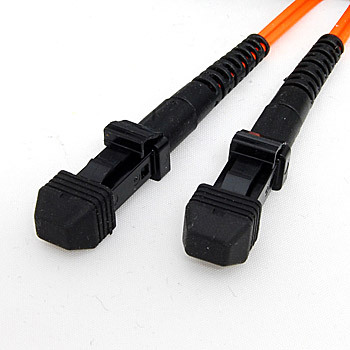
Mechanical Transfer - Registered Jacks (MT-RJ) look and work rather like RJ-45 connectors in how they latch. They are also fairly small and can be densely packed.
Core and Cladding
The optical fiber itself is a core strand of glass surrounded by cladding. This cladding helps protect the core but is also crucial to the function of the fiber. The outer diameter (the width of the fiber) including the cladding will all be 125 micrometers (or 0.125mm) while the core diameters are at the standard 50, 62.5 and 9 micrometers.
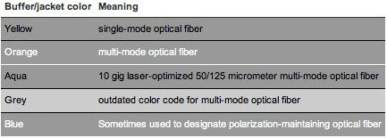
As mentioned earlier, single mode cables use the thinner optical fibers. Therefore, the 9 micrometer cores are all single mode, labeled as SM 9/125 fibers and have yellow jackets. Multi mode cables use the far thicker diameters of 50 and 62.5 micrometers with three different classes: OM1, OM2 and OM3 where OM stands for Optical Multi-mode. OM1 cables are 62.5 micrometers while OM2 and OM3 are both 50 micrometers. OM3 is differentiated from OM2 by being optimized for laser transceivers. The colors used for the cables are as follows: OM1 - orange jackets, OM2 - blue jackets, OM3 - aqua jackets.

 0
0

Fiber Optics 101: